Flow measurement technology in wastewater
Around 20 years ago, STEBATEC began to focus intensively on the topic of measurement technology for sewers. The decisive factors were the recurring questions of how accurate a flow measurement must be in the various measuring ranges and what price is appropriate for this, which system offers the customer an optimum cost-benefit ratio and how the measuring points should be designed so that they can be easily maintained. As an automation company, STEBATEC has also repeatedly had the task of throttling flow rates and controlling regulating devices based on the flow signals.
In the 1990s, the authorities placed new demands on measurement technology in wastewater treatment plants. At that time, Venturi measuring systems were used almost exclusively to record flow rates and the myth was widespread that the same measuring method must always be used to have the same error behaviour, at least at all measuring points. Over the years, however, it has become clear that the most suitable measuring method must be used for the different influences such as sewer network gradient, measuring range, minimum discharges, and sensitivity to contamination to generate satisfactory measuring results. Ideally, the measuring devices should not be influenced by construction tolerances and the systems should be able to monitor themselves after the initial calibration, e.g. by comparing individual partial signals with each other, which in turn requires measuring systems that measure and record at least two parameters (e.g. fill level and flow rate).
STEBATEC therefore searched intensively for solutions to measure better and more consistent results with significantly less complex measuring systems. Much of what was offered on the market was tried out, but without success, as the promised improvements could not be realised. An example of this is the partially filled measurement with the EMF measuring system. The disadvantages were simply too great during the operating phase. Limited measurement dynamics regarding minimum fill level and flow velocity, lack of zero-point stability and drift are just some of the problems with the partially filled EMF system.
The solution was to extend the EMF system with a simple pipe bend so that it could always measure full. After years of persuasion, the system was finally brought to market maturity and a satisfactory solution was presented to the customer, which was also considerably more cost-effective than a complete venturi design. From this point onwards, the measurement data was reliable and robust, but the permanent backflow resulted in increased maintenance costs and therefore further potential for optimisation. The systems were gradually improved and new technologies such as LDM measurement were developed.
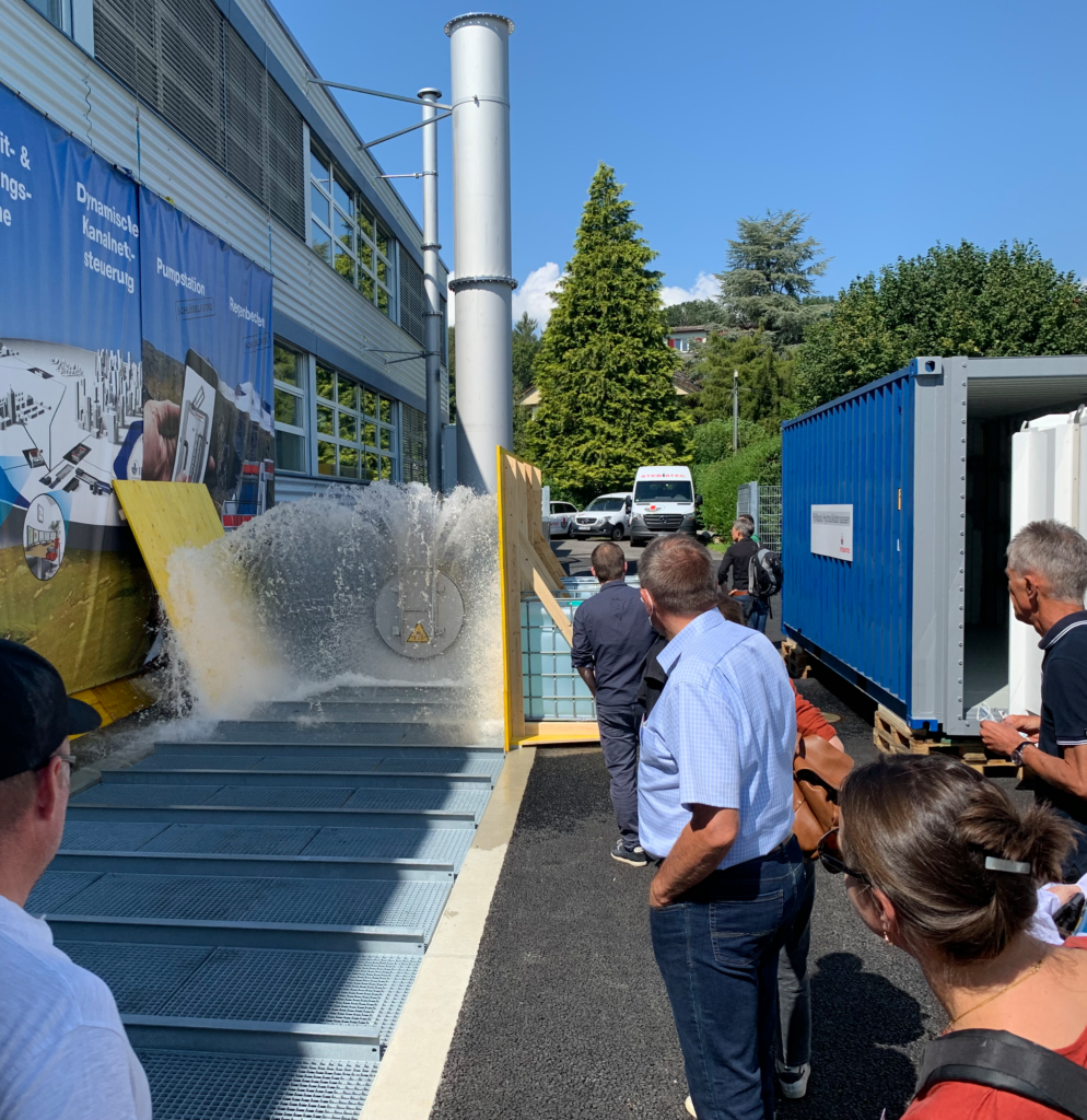
| Illustration: The hydraulics laboratory at STEBATEC’s headquarters in Brügg near Biel with the ability to continuously generate flow rates of up to 1600 litres per second. A visit to the factory is always worthwhile. |
In STEBATEC’s hydraulic laboratory, which has grown and been continuously optimised over the years, partially and fully filled flowmeters up to a maximum flow rate of 1600l/s can now be calibrated and tested. The hydraulic laboratory as a test facility has made it possible to constantly optimise the measuring procedures and develop new functions. For example, contamination can be simulated and recognised and reported at an early stage through signal evaluation before the measuring accuracy is impaired.
Operating cost billing in the catchment area of the Court wastewater treatment plant based on the polluter-pays principle
The wastewater from the municipalities of Champoz, Valbirse, Sorvilier and Court is channelled to the Court wastewater treatment plant. Thanks to the new STEBATEC measuring points, wastewater charges are now billed according to actual volumes.

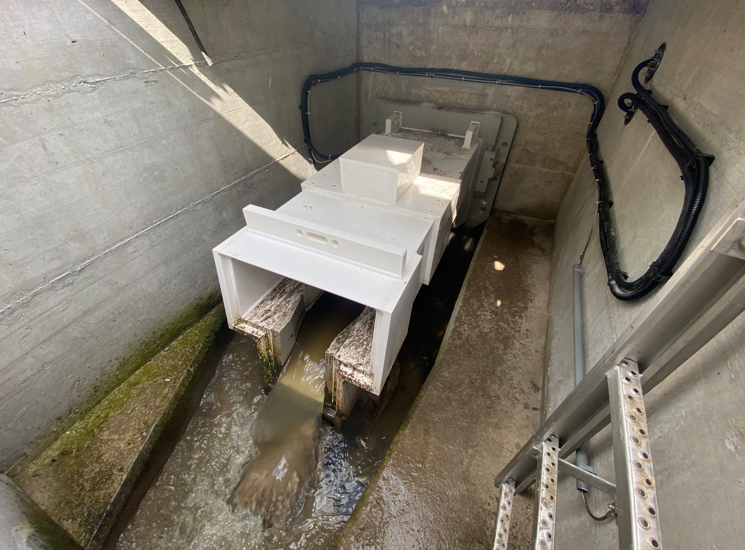
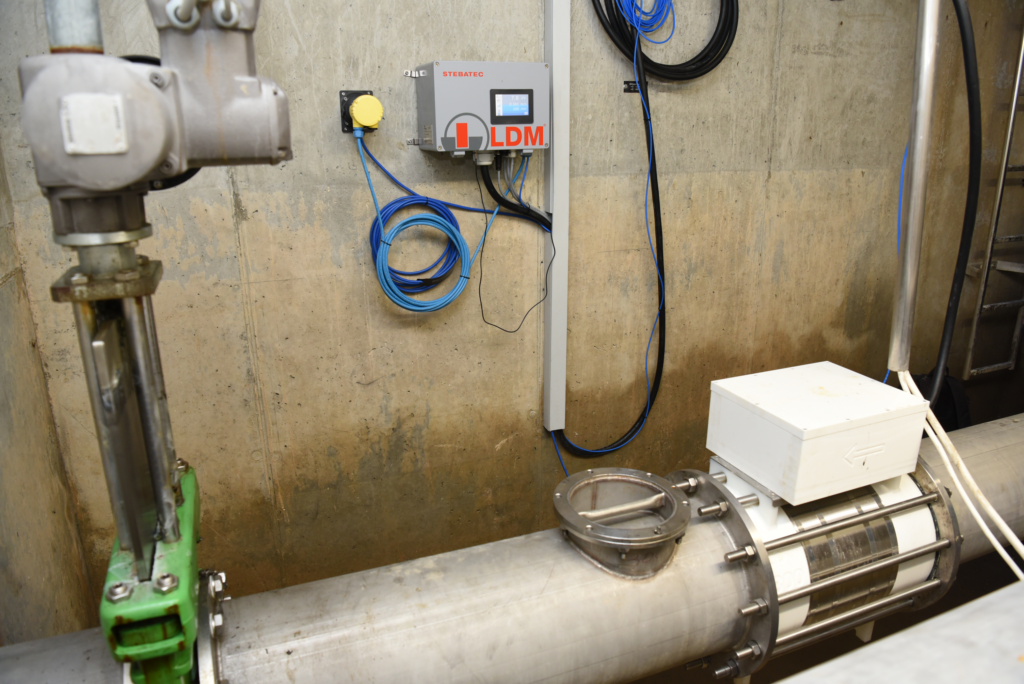
| Illustration: Compact measuring point with fully filled MID |
Each structure had its own specifications and criteria regarding the choice of measurement system to be used.
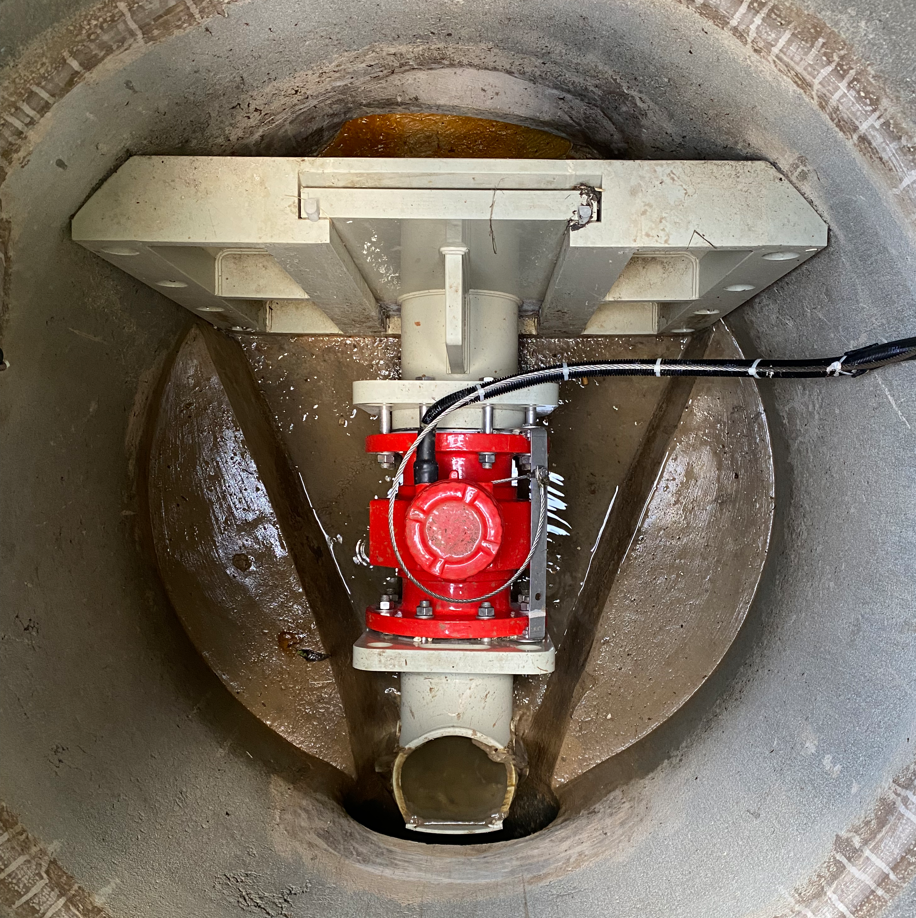
Due to the limited space available, an EMF measuring point for full filling was chosen in Champoz. This can be easily integrated into the manhole and, thanks to the robust EMF measurement technology, provides consistently accurate measurement results when full.
 As there is a sufficient sewer gradient, the basic build-up caused by the overflow bend is not a problem. Thanks to the system developed by STEBATEC, the measuring point can be mounted using a slide plate adapter and therefore requires no additional fixing points. The lifting points allow the device to be easily lifted out of the shaft with straps for maintenance purposes and then reinstalled.
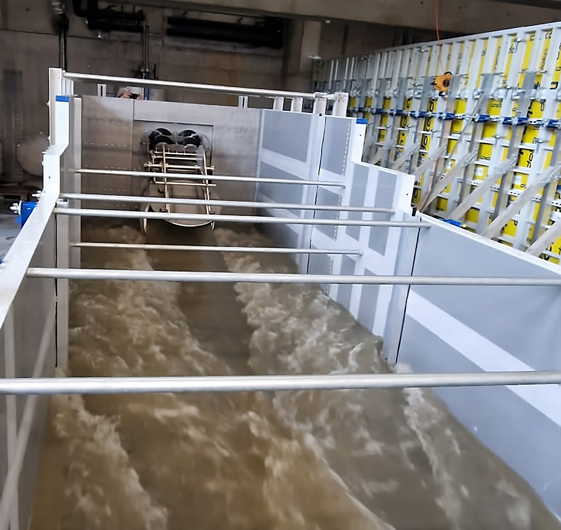
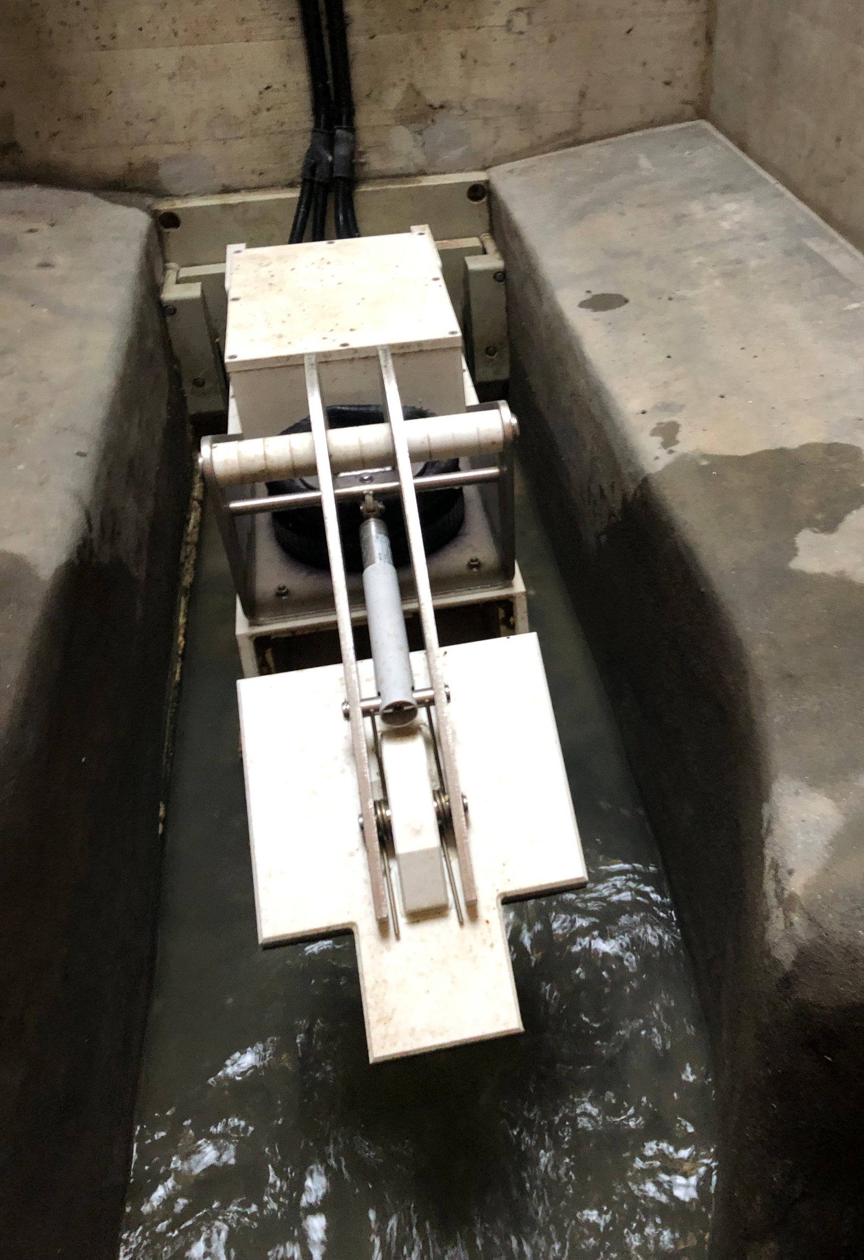
The Valbirse structure could be equipped with a TF stationary transit time difference measurement system as there was considerably more space available. The system measures in a partially filled state and does not generate any backwater. Ten flow velocity measuring sections distributed across the entire cross-section ensure maximum accuracy in flow measurement. The favourable arrangement of the sensors means that even small flows and levels can be measured accurately. The design with dry and rainy weather channel guarantees accurate measurement results over a large measuring range. The TF system was designed with a cover as a precautionary measure so that a butterfly valve (PNA) can be retrofitted later if required.

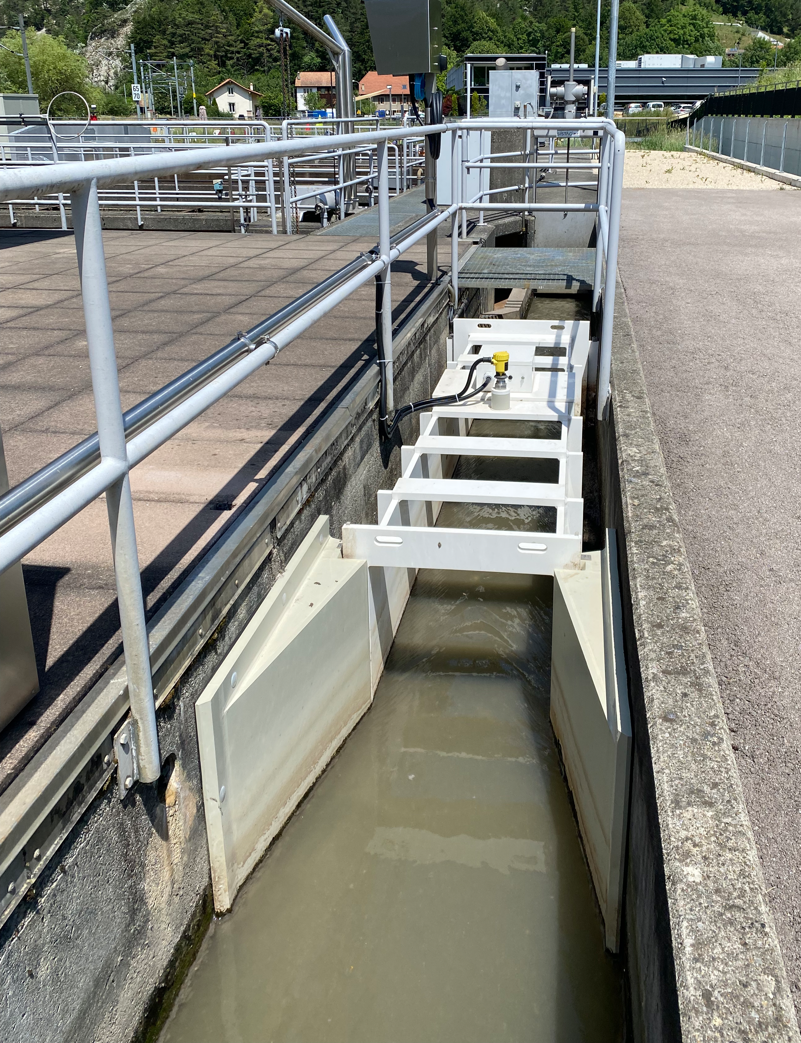
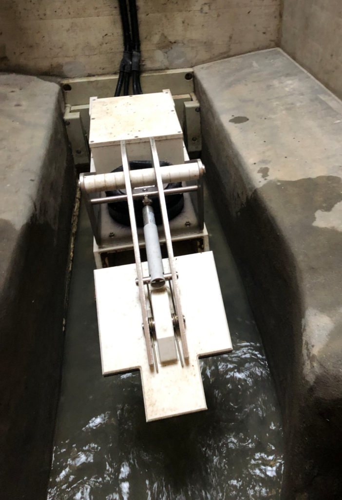
| Illustration: Partially filled stationary flow measurement TF with transit time difference measuring system and dry / rain channel for precise recording of flow rates over a large measuring range. |

| Illustration: Partially filled stationary flow measurement with pneumatically controlled butterfly valve |
As in Valbirse, a stationary transit time differential measurement was installed for the inlet measurement of the Court WWTP. The open design allows easy cleaning and inspection from above.
ll measurement data is transmitted to the ARAbella process control system, which was also installed by STEBATEC, including data communication. Quantities are billed directly in the process control system. This minimises the administrative workload.

| Illustration: Inlet measuring point of the Court WWTP. The open design is particularly favourable for cleaning and visual monitoring. |
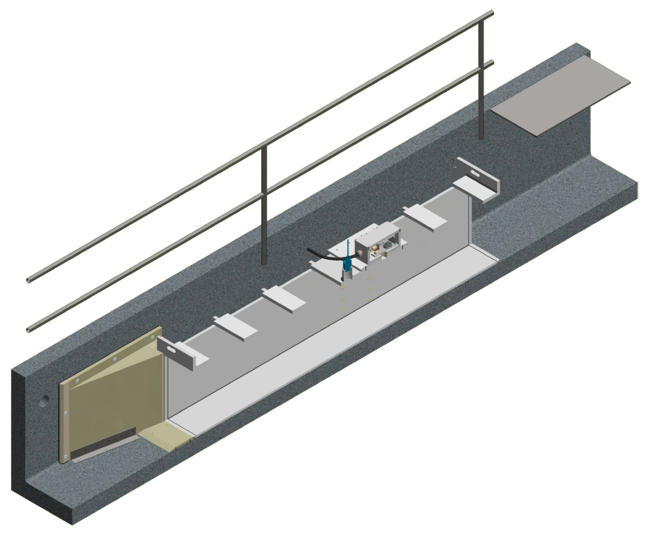
The design option of adapting the measuring point precisely to the existing structure avoids additional construction costs, as integration into the concrete channel can be carried out without any structural adaptations.
| Illustration: Cross-section through the measuring channel, which can be installed in the sound channel without additional construction work. |
State-of-the-art technology for the Institute of Hydraulic Engineering, Hydraulics and River Research IWA in Vienna
The University of Natural Resources and Life Sciences Vienna (BOKU) is one of the leading life science universities in Europe. STEBATEC was able to contribute to future research for the modern hydraulic engineering laboratory of the Institute for River Research at BOKU.
| Illustration: Control valve in action, the water of the Danube is precisely regulated to a specific flow rate. |
Thanks to the difference in water level of 3 metres between the Danube and the Danube Canal, up to 10,000 l/s flow through the hydraulic engineering laboratory without pumps and therefore without external energy, which is unique in the world. STEBATEC was involved in the planning at an early stage to ensure reliable flow control.
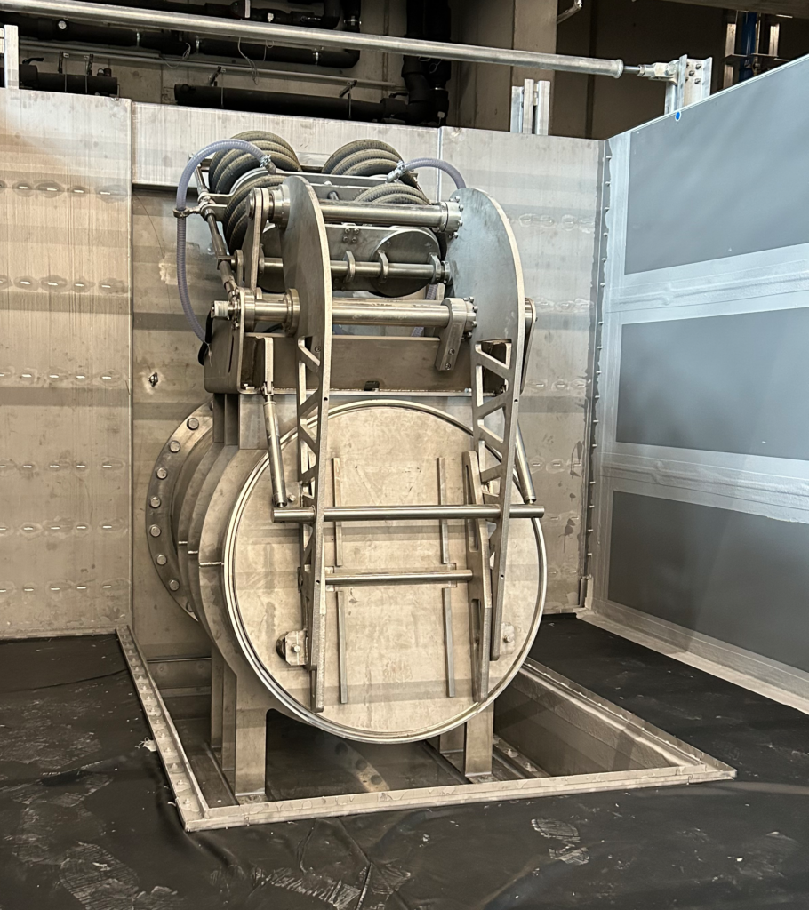
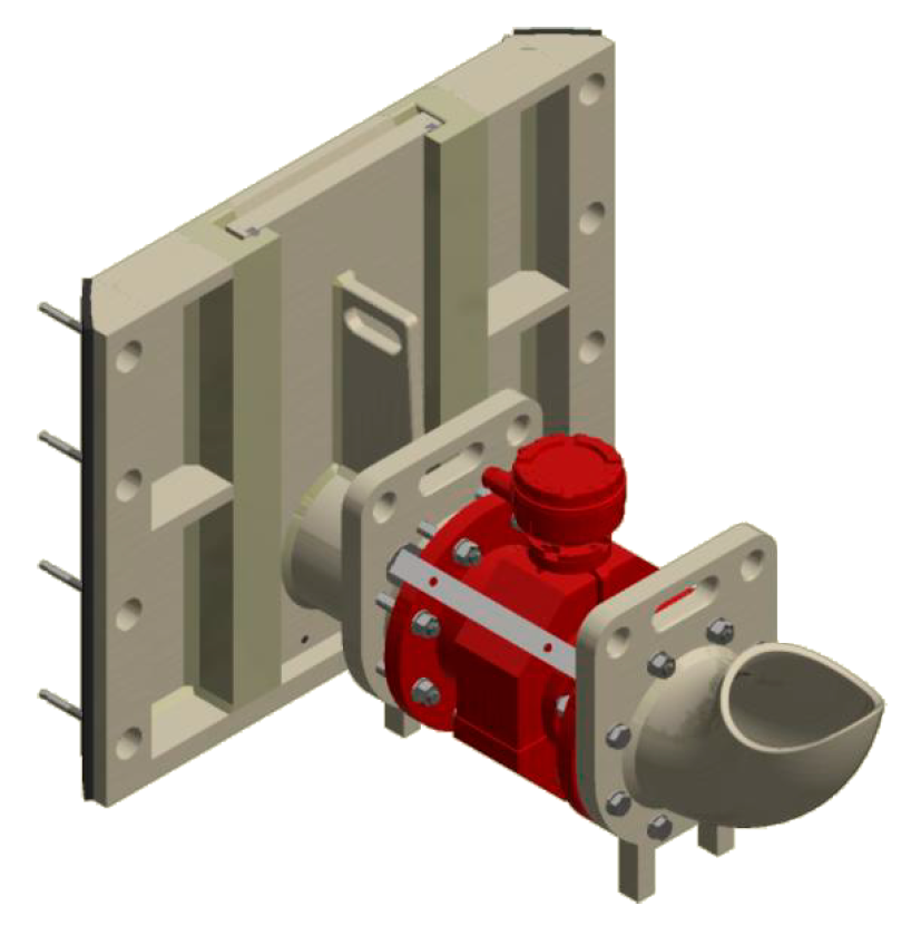
| Illustration: Pneumatically controlled butterfly valve with a diameter of one metre. The parametrisation possibilities open up new research opportunities for the water construction laboratory in Vienna. |
The pneumatic discharge control (PNA) was dimensioned in DN1000, which requires the application of considerable forces at a water pressure of 3 metres. The requirements for control accuracy are very high, the flow rates are approached by the PNA continuously over the entire flow range with the shortest actuating times.
The interaction of a correctly calibrated measuring point and the flow control, which can be parameterised down to the last detail using a pneumatic butterfly valve, is responsible for flawless water feeding. Even these dimensions can be precisely calibrated and tested in our in-house and certified hydraulics laboratory at our headquarters in Brügg CH.
The butterfly valve is pressurised with compressed air and moved into the position required by the water volume via a pneumatic actuator. The system receives the set values from the laboratory control system, which is connected via Modbus, or can be entered via the PNA touch panel. The intuitive user menu is easy to operate, and current parameters and measured values can be read via the visualisation.
The measurement data is permanently recorded and is available to the institution without gaps and for years to come.
Special requirement for the Walperswil culvert measuring point
The Walperswil culvert structure offered our design department the opportunity to develop a special solution for the customer.
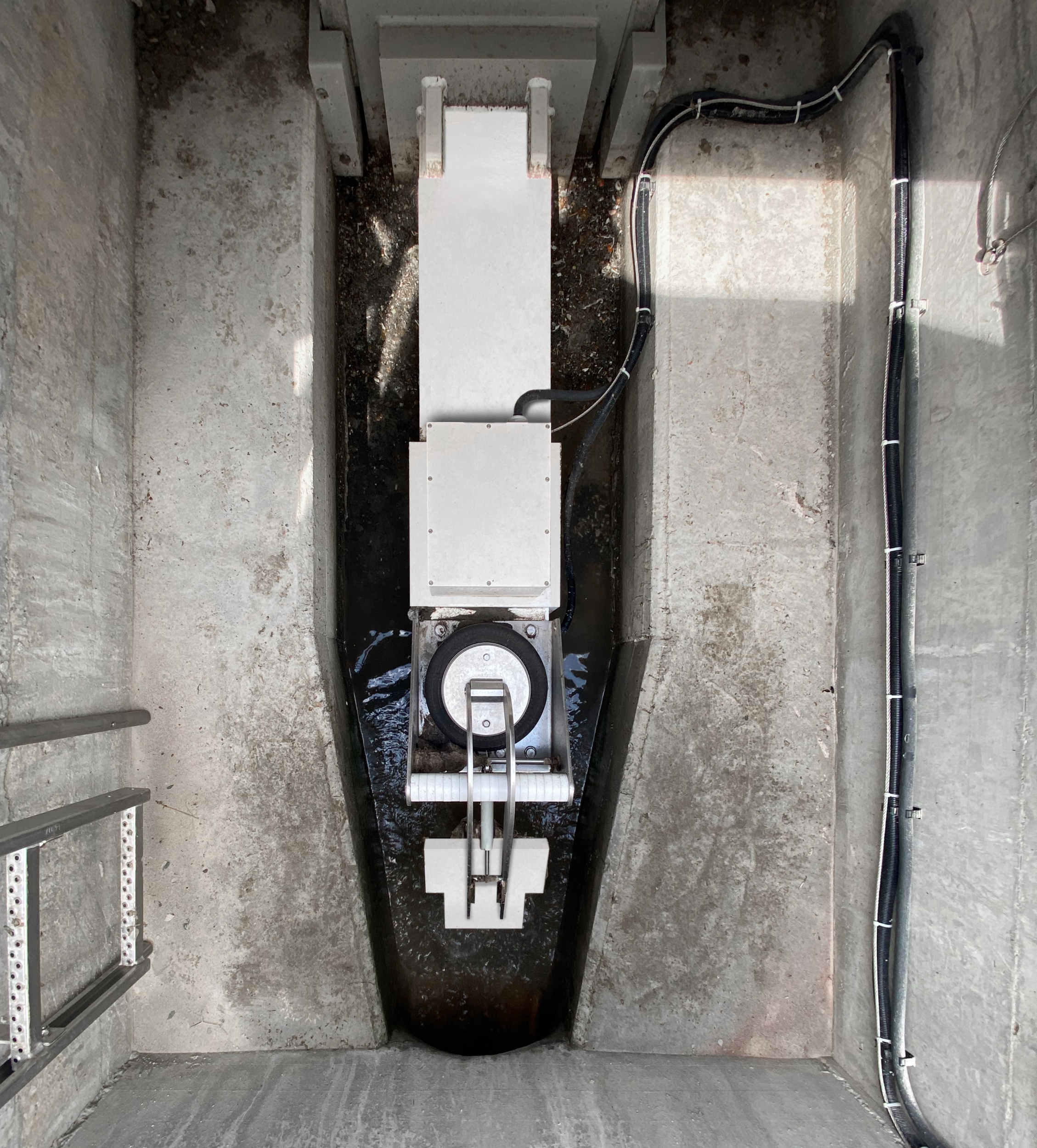
Thanks to the “dry weather channel” on the partially filled stationary flow measuring device, the water level and flow velocity remain measurable even at minimum night discharge. The dry weather channel was dimensioned based on calculations of the maximum discharge to be measured; in this specific case, discharges of up to 200 l/s can be measured with a maximum average deviation of 0.9 %, which also corresponds to the maximum discharge capacity of the culvert below. As soon as the culvert reaches its flow capacity, additional volumes of water are backed up, flow over the measurement and discharged via the laterally arranged sieves above the measurement.
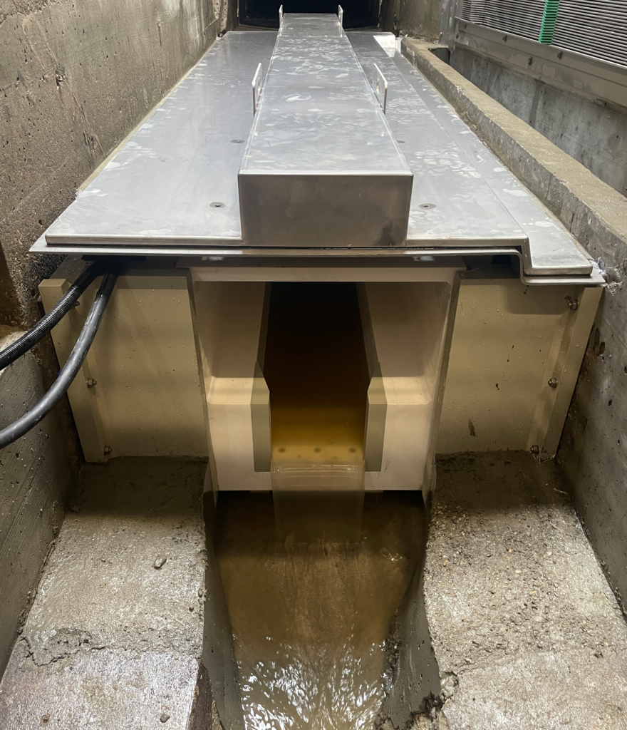
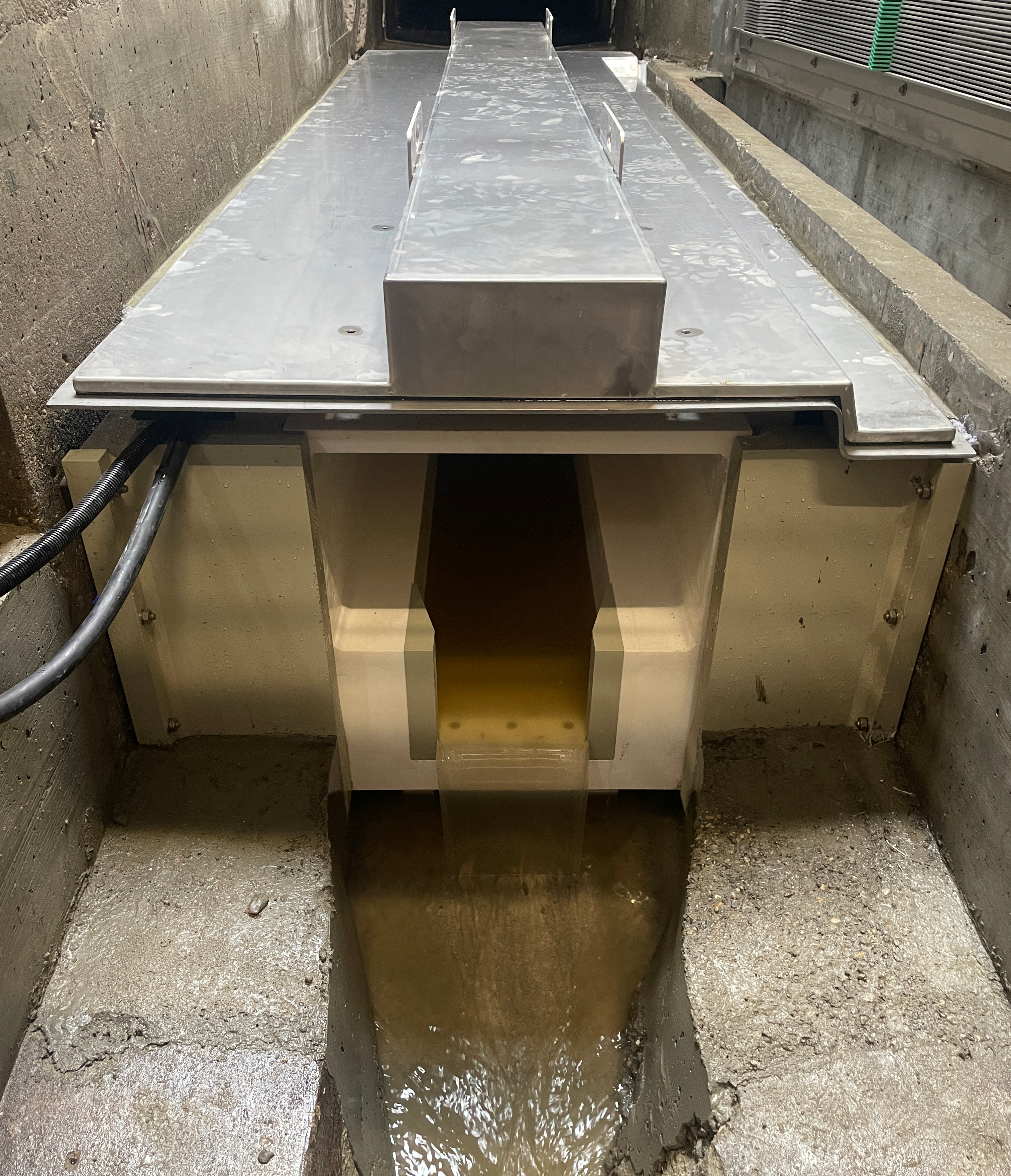
| Illustration: Measuring channel protected by chrome steel plate in the culvert structure in Walperswil. |
Lake Zug Region Water Protection Association
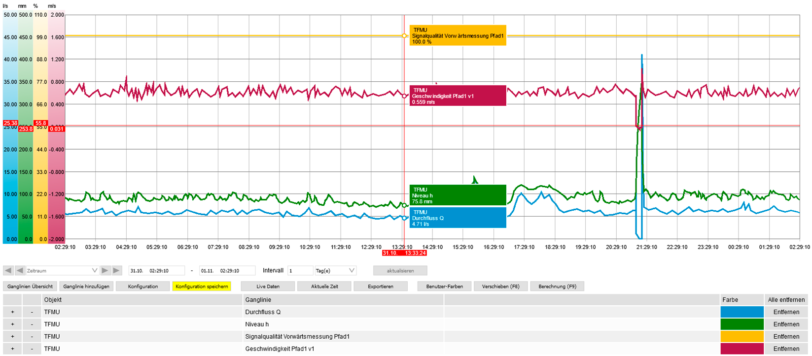
The new LDM measuring point in the Schmittli structure, below Ägeri, of the GVRZ was installed to achieve high measuring accuracy and reliability, especially with low night-time discharges. The LDM with a nominal diameter of 500 mm precisely and reliably records the discharge from a filling level of 26.1 mm. Ten flow velocity measuring sections distributed across the entire cross-section, whose signals are recorded in the integrated data logger of the transmitter over several years, ensure maximum accuracy in flow measurement. By recording and providing all pipe signals such as fill level, flow velocities and signal strength, the system monitors itself continuously and can be checked at any time.
Cleaning according to requirements
The robust and dirt-resistant system, which also has excellent properties against abrasion, minimises maintenance and service costs. An important feature of STEBATEC flow measurement technology is the automatic detection of contamination in the system, which is analysed via the signal quality. This means that the systems are only cleaned when they emit a contamination signal – the sensitivity of this signal is set at the factory so that cleaning is initiated before any possible impairment of the measurement quality occurs.
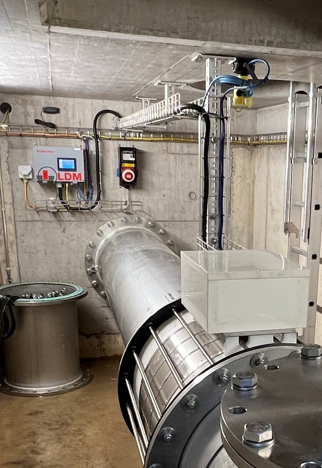
| Illustration: The Schmittli measuring and throttle structure at the GVRZ. The measurement signals are transmitted to the wastewater treatment plant’s process control system. The web interface integrated in the measuring transducer enables access to the data recording of all raw measurement signals for several years, for example. |
Large measuring range with constant precision in Matzendorf
The Falkenstein WWTP has been measuring flow rates in the sewer network for a long time. For various reasons, a new flow meter was sought that would not cause backflow, guarantee a large measuring range and be easy to operate.
After consulting the historical measurement data, an LDM with a nominal diameter of 300 mm was installed. With this size, flow rates from a filling level of 30 mm can be guaranteed to be measured. The measuring range is between 3 – 100 l/s. The minimum requirement is easily met with a gradient of less than 1%. A maintenance opening has been fitted near the sensor for maintenance purposes. This allows an insight into the pipe system and enables dirt to be removed without great effort.
| Illustration: The Matzendorf structure was equipped with an LDM measuring point including a maintenance opening. This always ensures trouble-free access to the sensors. |
Before the flowmeters leave the STEBATEC factory, they are calibrated in our in-house hydraulic laboratory. This laboratory can test and calibrate all flowmeters – regardless of manufacturer – with the required accuracy. The volume flow generated in the laboratory allows variable flow rates up to a maximum of 1600 l/s.
All data recorded during the testing and calibration process is saved for later traceability and stored for the legally prescribed period. The entire test is documented electronically in a test certificate and attached to the system documentation.
Calibration is based on the reference measured value compared to a flow measurement connected in series.
The accuracy of a flow measurement depends heavily on the hydraulic conditions. An approximation of the hydrodynamic flow curve is therefore the basis for a practical accuracy test, as different flow velocities in the measuring device also change the hydraulics. For this reason, the inlet section is adapted to the conditions on site.
A flow measurement must provide accurate results over the entire measuring range. Under no circumstances should an error be allowed to accumulate over each measurement step and influence subsequent measurements. For this reason, a two-stage test is carried out in our laboratory to ensure the plausibility of the results.
To collect precise data across the entire measurement spectrum, the test is carried out in two stages:
Level 1 / Area analysis increasing

Scanning of individual measuring ranges, ascending from a minimum flow rate, which still covers the lowest sensor pair with water, up to a maximum of 1600 l/s.
Level 2 / Area analysis declining

Scanning of individual measuring ranges, descending from the maximum flow rate of 1600 l/s to the minimum, which still covers the lowest sensor pair with water.
City of Winterthur equips three stormwater reservoirs with TF and PNA
Downstream of the Dättnau stormwater reservoir, which lies within the perimeter of the city of Winterthur’s sewerage network, the sewerage system was overloaded during heavy rainfall events, even though the Dättnau stormwater reservoir upstream was almost never full. The requirements for the pneumatic discharge control system were:- Reliable discharge measurement and control, as well as measurement technology in the reservoir
- ATEX-compliant design
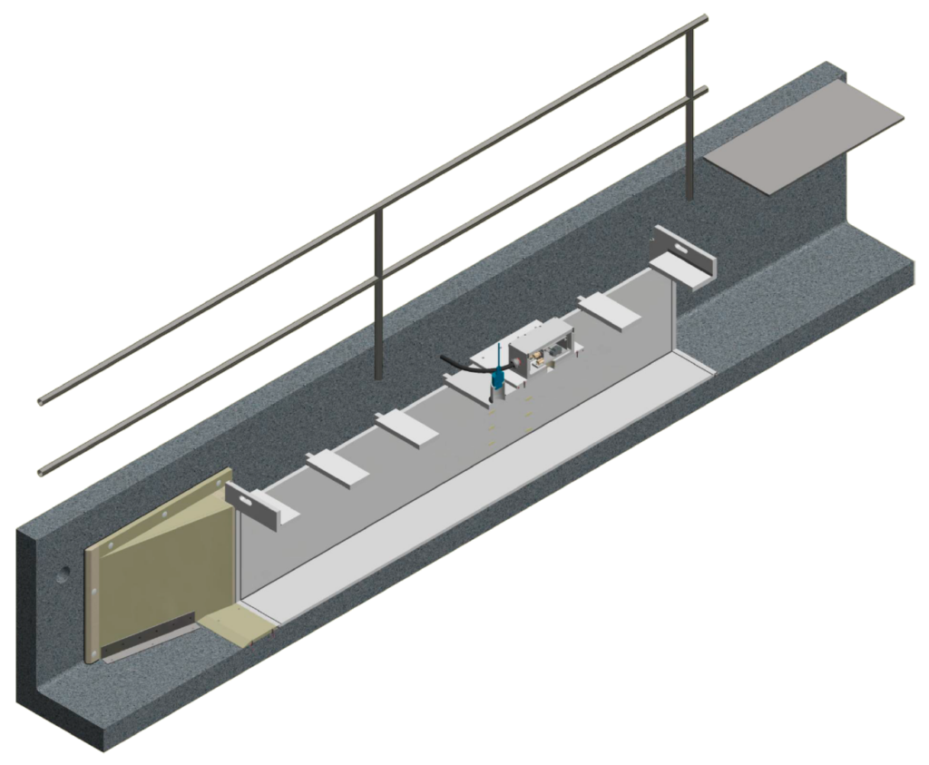
| Illustration: Pneumatic drainage control as part of an entire infrastructure in the structure, which is summarised in an ALLinONE control system. |

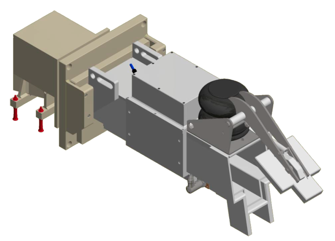
| Illustration: 3D view of the measuring point. The discharge control with LDM measurement impresses with its compact design. |